
Interface Relay KitHydronic Heat for Communicating Fan Coils
Item
AFAINTHWC01A

Systems with FE4B, FE5B, FCMB4, and FCMA5 communicating fan coils do not use 24VAC signals to communicate system operation commands. System control is accomplished through computer level commands on a system “bus” that requires fewer low voltage interconnecting wiring. System components that are not capable of communication through this bus require an interface kit. This kit provides interface of FE4B, FE5B, FCMB4, and FCMA5 communicating fan coils with Hydronic Heat equipment. NOTE: This kit will provide the necessary interface function when applied with communicating wall controls.
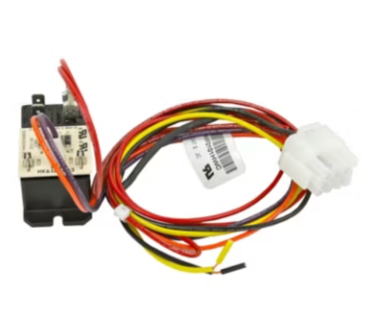
The Interface Relay Kit consists of: • a 22 VDC relay fitted with a rectifier circuit board that can be mounted within the fan coil • a wiring harness that is pre-wired to the relay and terminated with a 12-pin AMP Mate-N-Lok receptacle that connects to the fan coil’s heater control connector • two No. 16 AWG stripped leads for connecting the relay normally open contacts into the Hydronic system control circuit • two mounting screws • two wire nuts • instructions The wiring harness includes an ID device (270k resistor) that is recognized by the fan coil control as assigned to Hydronic Heat equipment. The relay provides switching control of the Hydronic equipment through its normally open contacts. Refer to the User Interface literature for further configuration information. NOTE: The relay provided with this kit may not be suitable for use with electronic control inputs using very low level current. Review the Hydronic equipment control power requirements prior to use of this kit. The minimum load rating for reliable switching of the relay contacts is 500 mA at 12VAC/VDC, additional loading may be required.
The Interface Relay Kit consists of: • a 22 VDC relay fitted with a rectifier circuit board that can be mounted within the fan coil • a wiring harness that is pre-wired to the relay and terminated with a 12-pin AMP Mate-N-Lok receptacle that connects to the fan coil’s heater control connector • two No. 16 AWG stripped leads for connecting the relay normally open contacts into the Hydronic system control circuit • two mounting screws • two wire nuts • instructions The wiring harness includes an ID device (270k resistor) that is recognized by the fan coil control as assigned to Hydronic Heat equipment. The relay provides switching control of the Hydronic equipment through its normally open contacts. Refer to the User Interface literature for further configuration information. NOTE: The relay provided with this kit may not be suitable for use with electronic control inputs using very low level current. Review the Hydronic equipment control power requirements prior to use of this kit. The minimum load rating for reliable switching of the relay contacts is 500 mA at 12VAC/VDC, additional loading may be required.
| Safety Standards | |
|---|---|
| California Prop 65 | Yes |
| Weights and Dimensions | |
|---|---|
| Operating Weight (lbs) | 1 | Exterior Dimensions (D) (inches) | 5.000000 | Exterior Dimensions (W) (inches) | 5.000000 | Exterior Dimensions (H) (inches) | 3.000000 | Shipping Weight (lbs) | 2.000000 |